1.
Table of content
2.
Introduction
3.
Removal
4.
Assemble
5.
Installation
6.
Test running and commissioning
7.
Financial Statement
8.
Safety Precaution
9.
Conclusion and recommendation
10.
References.
11.
Appendix

500KVA POWER GENERATOR
(front view)
2. INTRODUCTION
The removal,
assembling, installation, test running and commissioning of 500KVA power generator
is carried out with five men, one Engineer, two Technologies and two
Technicians are selected to carry out the operation.
3. REMOVAL
Removal is a process
of dismounting and disengaging the generator from the foundation, so as to
allow the crane to lift it up, as the following step is taking into
consideration.
- Schedule cranes and freight for day of decommissioning
- Disconnect power from main breaker for all equipment involved
- Proceed with disconnecting the primary electrical wiring to and from the generator, ATS (Automatic Transfer Switch) and other equipment. caution, remove all wires properly from contacts - we do NOT cut or rip so as not to end up cutting the wrong wires and damaging the equipment, and/or potentially spilling fluids and getting copper shards and various wiring debris everywhere
- Terminate all wires properly to close connections, plus re-label everything
- Remove all chemicals and fuels and dispose of properly
- For Data Centers – remove all additional UPS and HVAC equipment through similar process - properly disconnecting and terminating incoming and outgoing wires, de-constructing flooring, rack removal, etc.)
- Update breaker panel labels, restore power to the area and leave everything like new
4. ASSEMBLY
An assembly
line is a manufacturing process most of the time called a progressive assembly in which parts usually
interchangeable parts are added as the semi-finished assembly moves from
workstation to workstation where the parts are added in sequence until the
final assembly is produced. By mechanically moving the parts to the assembly
work and moving the semi-finished assembly from work station to work station, a
finished product can be assembled faster and with less labor than by having
workers carry parts to a stationary piece for assembly.
The
principles of assembly are these:
(1) Place the tools and the men in the sequence of the
operation so that each component part shall travel the least possible distance
while in the process of finishing.
(2) Use work slides or some other form of carrier so that
when a workman completes his operation, he drops the part always in the same
place which place must always be the most convenient place to his hand and if
possible have gravity carry the part to the next workman for his own.
(3) Use sliding assembling lines by which the parts to be
assembled are delivered at convenient distances.
 |
|||
5.
Installation
Method Statement for Installation of 500KVA Power
Generator
The purpose of generating this Method Statement is
to define the procedure step by step to implement the correct practices
for Installation of Diesel Generator Set through the guide
line contained herein so as to ensure that the job execution complies with
the requirements and serves the intended function to satisfactory level.
TOOLS
/ EQUIPMENT:
- Crane
of suitable capacity of (4000kg) and arrangement in line with the
Manufacturer’s recommendations
and as required at site. - Forklift of suitable capacity.
- Chain Pulley Block.
- Portable hand tools.
- Portable Drilling Machine/ Grinding Machine & Angle Cutter.
- Spirit Level.
- Crimping Tool
HANDLING
and STORAGE OF DIESEL GENERATOR SET:
On receipt of the Diesel Generator Set and
accessories at site, necessary precautions shall be taken for unloading,
shifting and storage, as follows:-
- Material is stored in a covered / dry space at all the time.
- Materials received at site were inspected and ensured that the materials are as approved material submitted.
- Any discrepancies, damage etc., found was notified and reported for further action.
- Site Engineer (Electrical) has to ensure that all Equipment used at site are free from any damage or deformity of any kind. Any minor damages observed were repaired suitably and in case if the repairs could not be done properly, the Equipment was replaced.
SHIFTING
THE UNITS FROM STORAGE YARD TO THE GENERATOR LOCATION
- After the activities under the general installation procedures are completed the unit was loaded from the storage place, on the suitable trailer, by the suitable loader Forklift and Crane, to shift the respective generator location.
- The units was offloaded near the generator room (Substation 1) north side, and were shifted on the respective foundations by the suitable loader (Forklift) over the ramp, which is being installed to take units from outside to inside.
- Proper care to secure units, while above shifting loading/unloading as well as placing was carried out with at most care and precautions as required for the safe operation.
INSTALLATION
PROCEDURE FOR 500KVA POWER GENERATOR
To carryout installation activities for diesel
generator below mentioned procedures are taking into consideration to
follow-up step by step in sequential manner.
- Pre delivery inspection was performed to ensure no damage is occurred in transit to all Generator Set components.
- Prior to start installation, Site Technologies (Electrical) were ensured that approved shop drawings related to the installation area are referred and that required materials are available at site as approved.
- Site Engineer (Electrical) was ensured that all the materials are received at site as per approved material submittal and verify the ratings.
- The name plate was checked against equipment data sheet to confirm conformity with the approval.
- Material Inspection Request should be raised for material verification upon delivery at site.
- Ensure all civil works are completed for the area including floor paint to carry out the installation, and clearance is obtained from respective authorities to precede further installation of generator set.
- Installation procedures were followed as manufacturer’s recommendations.
- Installation works was carried out only with respect to approved shop drawings of latest revision.
- Diesel Generator Set was off loaded to the place nearest to the installation and protected properly from dust & environment, etc.
- Machine foundation design, which is also known as machinery foundation design is accomplished to protect the adjacent foundations of the structure from the vibration of the rotating or vibrating machine.
- Block type machine foundations consist of a pedestal resting on a footing. The foundation has a large mass and a small natural frequency was build.
- Prior to installation, the foundation was checked for cleanliness and level.
- The Site Engineer ensured that orientation of 500KVA Power Generator set as per approved shop drawing Exhaust duct & fuel oil pipe installation was comply with the relevant clauses of specifications and as per manufacturer recommendation.
- Alternator neutral terminal & Body was connected with external earth as per approved shop drawing.
- Alternator control panel was connected as per approved shop drawing and manufacturer recommendations
- Cable connections between alternator, control panel and Emergency Main Distribution Board were done as per approved shop drawing.
- From Emergency Main Distribution Board to other sub emergency panels, Power Distribution work were done as per approved shop drawing
- Installation of muffler, fuel supply system, exhaust ducts, circuit breaker installation connections to BMS and control wire was carried out as per approved specifications.
- Pre & Post installation starts up and commissioning at site using available site load was performed in coordination with the manufacturer’s local dealer in the presence of consultant representative as appropriate.
- Detailed procedure shall be submitted for testing pre-commissioning and commissioning checks for consultant’s approval prior to commissioning of generator set Applicable operating instruction, service manuals, and recommended spares was submitted in General Manager.
- Required power and control termination was carried out as per approved drawings.
- After inspection of Generator Set proper care was taken to protect the unit from dust by suitable covering, and were further released for the Testing work.
6.
TEST RUNNING AND COMMISSIONING.
Method Statement for Testing and Commissioning
500KVA Power Generator
The purpose of this procedure is to define the step
by step method to implement the correct practices for the testing,
pre-commissioning and commissioning of “500KVA Power Generator”.
Through the guidelines contained herein so as
to ensure that the job execution complies with the project requirements
and serves the intended function to satisfactory level.
Required Equipments:
- Portable Hand tools
- Step Ladder
- Load Bank & cables
- Computer
- Multi-meters
Pre-commissioning (Test running)
Procedure for Diesel Generator
Ensured that the Generator installation is complete
and mechanical completion is approved.
Ensured that no damage has occurred between
mechanical completions and pre-commissioning.
Repair / replace damaged components, was taken into
consideration as follows:
1.
Check for proper installation of
vibration isolators for the generator.
2.
Ensured the installation of the
generator exhaust piping is complete & approved.
3.
Ensured that the air intake system to
the generator room is complete.
4.
Ensured that the Fuel oil piping with
fuel pump installation is complete, pressure tested & approved.
5.
Ensured that installation of the
generator exhaust ducting is complete & approved.
6.
Ensured proper installation of the
exhaust muffler.
7.
Ensured that the cables to the generator
are properly terminated & are tight & secure.
8.
Ensured that all the control cables
between the generator EMCP and generator sensing panel are completed &
terminated at both ends.
9.
Ensured 240 V A/C supply is provided to
the generator sensing panel.
10.
Ensured all ducting, piping & conducting
to the generator are connected vide a flexible connector to avoid the
transmission of vibration to the service connection.
11.
Ensured that the battery charger is
installed & the batteries are charged.

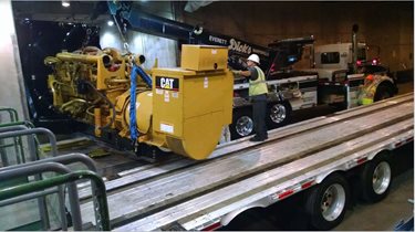
500KVA Mikano
Power Generator (side view)
COMMISSIONING PROCEDURE FOR DIESEL
GENERATOR
1.
Ensured that all the pre-commissioning
checks are carried out successfully and the fuel oil system & pump is
commissioned.
2.
The priming of the fuel oil pumps was
checked.
3.
The batteries was connected & the
Emergency Stop Function and Crank Termination was checked as follows:
Emergency Stop
(a) Start the engine
(b) Run the unit under no load condition
(c) Press emergency stop
(d) Confirm the generator set stops immediately
Crank Termination
(a) Reset all alarm / shut down by turning engine control switch
to OFF/RESET position.
(b) Disable fuel injection system
(c) Start the generator set
(d) generator set was confirmed by trying to start for 3 cycles (10 seconds start
and then 10 seconds stop).
(e) Confirm generator over crank shut down.
4.
The engine was simulated to running
condition & the oil pressure trip, high jacket water trip & over
speed trip was simulated and checked as per attached manufacturer’s
guidelines.
5.
The AVR (Automatic Voltage
Regulator) fuses were disconnected.
6.
The DC (direct current) polarity of
engine controls was checked.
7.
The setting of the governor was recorded
in line with manufacturer’s guidelines.
8.
The engine was started and adjusted for
stability. The startup procedure was as per manufacturer’s guidelines.
9.
After adjusting the engine was stopped
& the rated speed was connected and the stability was adjusted again.
Engine stability adjustment procedures were as manufacturer’s guidelines.
10.
The AVR (Automatic Voltage
Regulator) fuses were installed and the engine was started again.
11.
The voltage potentiometer was adjusted
and the volt droop potentiometer was set as per manufacturer’s guidelines.
12.
The oil pressure, temperature, speed,
volt, frequency, phase sequence, fuel pressure, battery voltage &
battery amps was recorded.
13.
The alarms & trips were tested by
shorting fault contacts.
Electronic Governor
- The low idle speed, rated speed, start fuel limit and ramp time was measured and recorded against the setting value.
- The actuator compensation, gain, reset, droop, load gain and over speed settings were recorded against the setting value. All setting values were as per manufacturer’s guidelines.
Cooling water system
- The system was filled with potable water with rust inhibitor and the air was purged.
- The water level was checked and any leakages in the system were checked.
- The engine was run at no load and the circuit was checked for any leakage.
- The operation of the low coolant level sensor was checked as per manufacturer’s guidelines.
- The jacket water temperature high alarm & shut down simulation were checked as per manufacturer’s guidelines.
Fuel Oil system
- Fuel oil system with fire valve, 2 ports, motorized valve, pressure switch & level sensor were checked for proper installation with alignment.
- The tank was filled and the system was checked for leakage.
- In case of a leak, the leak was detected by a drip tray mounted float switch which was connected to sound an alarm.
- The engine was run at no load and the circuit was checked for any leakage.
- The fuel oil high level & low level alarm switch was checked.
- The fuel oil high level & low level pump stop switch was checked.
Lube Oil system
- The system was filled with the oil recommended by the manufacturer.
- The oil level was checked and it was ensured that there are no leaks in sump and drain.
- The engine was started and the oil pressure was observed as per manufacturer’s guidelines.
- The engine was run at no load and the circuit was checked for any leakage.
- The engine was stopped and the oil level was checked again.
- The lube oil high temperature alarm and shut down was checked as per manufacturer’s guidelines.
- The lube oil low pressure alarm and shut down was checked.
Generator Load Test
- The load test on the generator was carried out increasing the load from 0% to 100% in steps of 25% using load bank.
- At 0% the run time was 5minis, for 25%- 10 mins, for 50-10 mins, for 75%- 3 Hrs & for 100% – 3 Hrs.
- The fuel consumption 30 l/hr, actual 450 KW, line voltage 380V, and 1500/1800RPM and battery voltage 12V was recorded at agreed intervals of run time.
Digital Voltage regulator (DVR)
- It was confirmed 24V DC is available for the digital voltage regulator.
- The programmable parameter was set to the default values as recommended by the manufacturer.
- The generator was started and the view parameters and the status of the switch parameters were recorded.
Generator Sensing Panel
- During simulation test check the appropriate annunciation windows/alarms LEDs in the generator sensing panel are illuminated.
- Checked the ON & OFF function of the generator from the sensing panel by simulation.
- Checked the OFF function of the generator by the emergency stop push button.
Automatic Transfer Switch (ATS)
- Checked on the voltage availability in the line side of the ATS. If the voltage is available, and the changeover switch remains unchanged.
- When the voltage is not available in the line side, checked on signal from the ATS to the generator sensing panel to start generator.
- Once the generator full voltage is available at the ATS emergency terminals, checked the ATS change over to generator supply automatically.
Basic
Specification
|
Standby
Power
|
440KW/550KVA
|
|
Color
|
White
|
|
Prime
Power
|
400KW/500KVA
|
|
Application
Area
|
Industry project, hospital, hotel,
etc
|
|
Frequency
|
50HZ
|
|
Rated Voltage
|
240/380V
|
|
Fuel
|
Diesel
|
|
Rate
|
<1000
|
|
Output
Type
|
AC Three Phase
|
|
Rated
Current
|
>150
|
|
Maximum
Power
|
>70
|
|
Fuel consumption
|
30L/hr
|
|
Total
oil Coolant capacity
|
27L
|
|
Alternator Exciting type
|
Brushless self exciter AVR
|
|
Battery Rating Capacity(AH)
|
2X120AH 12V
|
|
Dimension Generator set dimension(LXWXH)
|
2400x830x1430
|
|
Weight Generator set Net Weight (kg)
|
1700
|
7.
FINANCIAL STATEMENT
THE COST IMPLICATION AND LOGISTICS.
In respect of the removal, assembly,
installation, test running and commissioning of Mikano 500 KVA power generator
from General Machine Works Rigachikun to No 10 Rock road Malali GRA Workshop
the total cost is as follows:
|
S/N
|
RANK
|
No
Of Personal
|
Cost
Per Day (₦)
|
No
Of Days Spend
|
∑
cost (₦)
|
|
1
|
Engineer
|
1
|
20,000.00
|
6
|
120,000
|
|
2
|
Technologist
|
2
|
16,000.00
× 2 ꞊
(32,000.00)
|
6
|
192,000
|
|
3
|
Technician
|
2
|
12,000.00
× 2 ꞊
(24,000.00)
|
6
|
144,000
|
|
Total
|
456,000.00
|
||||
Cost
of material handling =
30,000.00
Cost
of loading the generator by crane = 15,000.00
Cost
of unloading the generator by crane = 17,000.00
# 132,000.00
The total cost is 456,000.00 + 132,000.00 = #
588,000.00
The ground total is five hundred and eighty eight
thousand naira only.
8. SAFETY PRECAUTIONS
A. General hazard
1. Installation, repair and maintenance should
always be accordance with the manufacturer’s instructions and recommendation.
2. Exhaust fumes emitted by generator sets contain
poisonous gases like carbon monoxide that can be life threatening and result in
death. Exhaust system must be properly installed, adequate ventilation must be
provided to ensure unobstructed flow of cooling and ventilating air, and
emission must be directed away from inhabited zones.
3. The area around the generator must be clean and
free of clutter and any combustible material that can be hazardous.
4. The equipment must be regularly inspected and
defective or damage parts must be replaced in a timely manner.
5. It is essential that the operating personnel
remains alert at all times while working with the generator.
6. The unit should not be opened or dismantled while
it is functioning. Moving or hot parts should not be tampered with. Battery
cables should be disconnected before proceeding to work on the generator to
eliminate any possibility of an accidental start- up.
B. electrical hazards
1. All power voltage supplies should turned off at
the source while installing or servicing the generator.
2. All electrical connections, such as wires, cables
and terminals must be properly insulated and covered, and should not be touched
with bare hands or while in contact in water.
3. The frame of the generator and any external
conducting parts should have proper grounding/earthing. This should never be
disconnected.
4. Wiring, cable and cord sets must be of the recommended
capacity. Precaution
taking
When carry out the practical all the necessary
precaution are taking into consideration, such as:
I.
Ensuring that all the work men are in
there personal protective equipment
II.
That all the material handling are in
good working condition
III.
It was ensured that the foundation are
inspected by the civil engineers
9. CONCLUSION AND RECOMMENDATION
Recommendation
Diesel engines running at 1800/1500 RPM and water
cooled, should be given major overhauling on every 12,000 to 13,000 hours, so
for every 150 hours there is need for service maintenance.
Due to inadequate facilities available which cause
inefficient operation when carry out the contract, it is recommended there
should be an adequate source of material handling in the workshop.
Conclusion
The removal, assembly, installation, test running
and commissioning was successful done with the cooperation of five men
technical committee.
10.
REFERENCES
1.
HORSLEY, D.
Process Plant Commissioning, a User Guide, Institution of Chemical Engineering,
1998.
2.
FARES, F.,
MONTENEGRO, B., PRATES, A., Commissioning
of Oil & Gas Projects – Current Status, Evolution and Trends. in:
Rio Oil & Gas 2010, Rio de Janeiro, Brazil, set 2010.
3.
BENDIKSEN, T.,
YOUNG, G. Commissioning of Offshore Oil and Gas Projects: The Manager's
Handbook, Author House Publishers, 2005.
4.
Hoffman, Chris (27 July 2013). "How to Avoid
Installing Junk Programs 2015.
5.
Bursary
office, Kaduna Polytechnic, Financial Report 2017.
6.
Electrical Engineering Department, Kaduna
Polytechnic, Consultancy Visit 2017.

Appendix:
Complection of Contract.
Certified
and Accepted by Engr. M.T. Sambo (General Manager).
No comments:
Post a Comment